GDT: Global Descriptor Table
Over the next few chapters, we’ll replace the structures provided by UEFI with Ymir’s own versions. This replacement is a necessary step for freeing the UEFI-reserved regions to implement Ymir’s memory allocator. Our honorable first target is GDT.
important
The source code for this chapter is in whiz-ymir-gdt branch.
Table of Contents
- Overview of GDT
- Linear Address and Segment Selector
- Segmentation in 64-bit Mode
- Segmentation in Ymir
- Summary
Overview of GDT
GDT: Global Descriptor Table is a table structure used to configure segmentation1. Segmentation is a feature that divides memory into several logical blocks. In x86-64, there are three types of addresses, and they are translated as follows:
graph TD
    Logi[Logical Address] --> |GDT / Segment Selector| Lin[Linear Address]
    Lin --> |Page Table| Phy[Physical Address]
A Logical Address is the address directly handled by software. A Linear Address is the result of applying segmentation to a logical address. A Physical Address is calculated by MMU: Memory Management Unit translating the linear address using page tables.
We’ve already implemented page tables in Surtr's Simple Page Table chapter. In this chapter, we’ll focus on configuring GDT to handle the conversion from logical to linear addresses.
Linear Address and Segment Selector
A linear address is a 64-bit address calculated by applying segmentation to a logical address2. Logical to linear translation uses both GDT and a Segment Selector. GDT and segment selectors provide information such as the segment’s Base, Limit, and Access Rights.
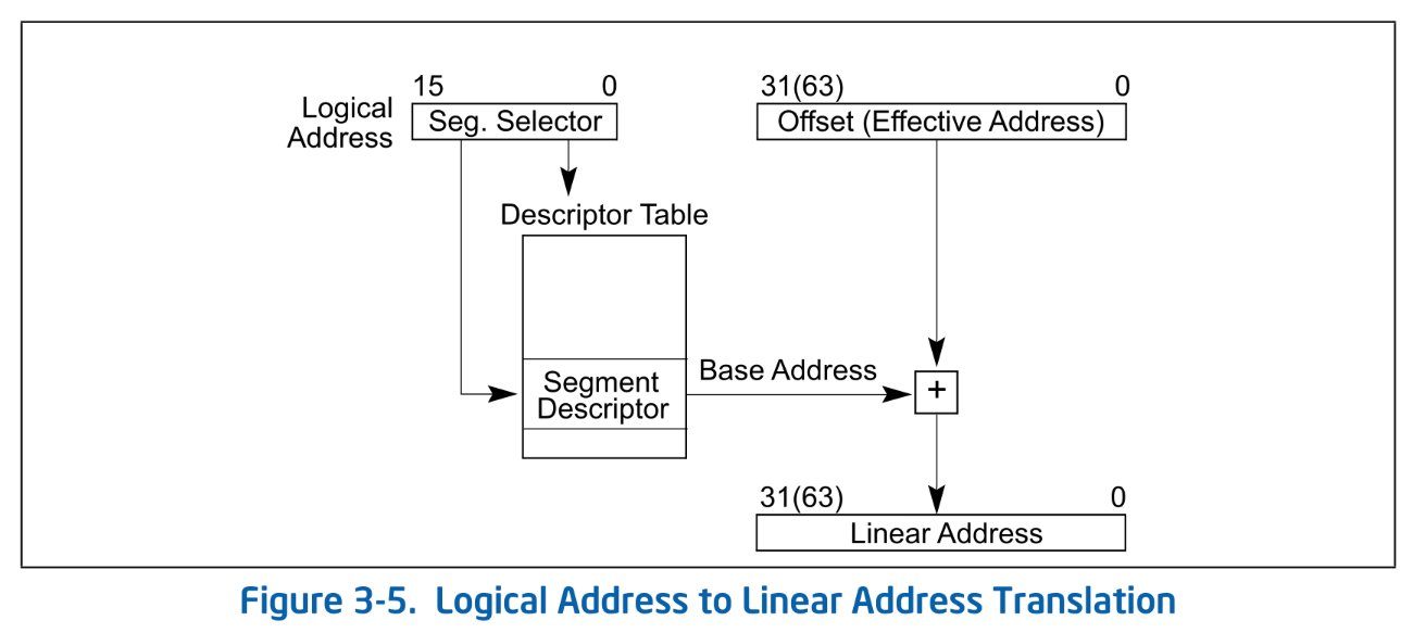 Logical Address to Linear Address Translation. SDM Vol.3A 3.4
Translation follows these steps:
- Obtain a segment selector from a Segment Register.
- Obtain the GDT entry pointed to by the segment selector.
- Retrieve the Base from the corresponding GDT entry, add it to the offset part of the logical address, and compute the 64-bit linear address.
Segment Register
In x64, there are six segment registers: CS, SS, DS, ES, FS, and GS. Each register consists of a Segment Selector and a Hidden Part:
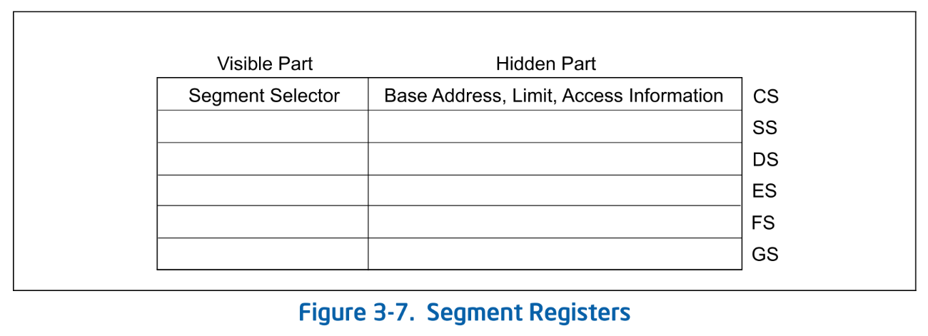 Segment Registers. SDM Vol.3A 3.4.3
A segment selector is an index pointing to an entry in the GDT. Based on this index, the corresponding GDT entry is retrieved, and the Base from that entry is used to compute the linear address. The hidden part caches part of the GDT entry pointed to by the selector. During address translation, since the GDT entry is already cached in the hidden part, the CPU no longer needs to fetch it from the GDT3.
Only the selector can be set directly from software. When the program sets the selector, the CPU automatically fetches the corresponding entry from the GDT and caches it in the hidden part.
note
In addition to address calculation, the following checks are performed during logical to linear translation:
- Whether the offset part of the logical address exceeds the Limit.
- Access Right of the segment is valid
Global Descriptor Table
GDT is a table that defines each segment. It is analogous to the Page Table used in linear to physical address translation. A GDT entry is 64 bits and has the following structure:
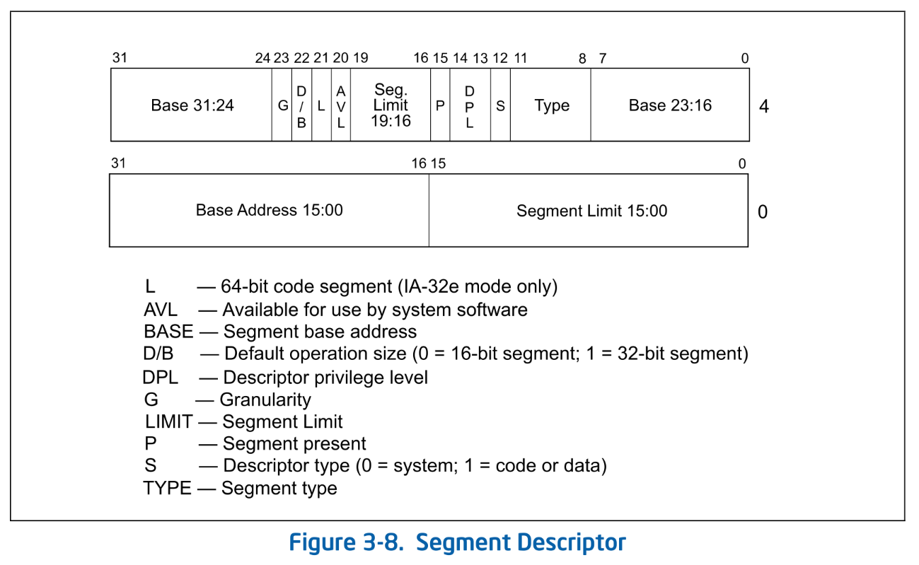 Segment Descriptor. SDM Vol.3A 3.4.5
A GDT entry defines the following main information for each segment:
- Base: Start linear address of the segment
- Limit: The size of the segment. The unit changes depending on the Granularity.
- DPL (Descriptor Privilege Level): The privilege level of the segment. Access is allowed only if the CPL is less than or equal to the DPL.
The address of the GDT itself is stored in the GDTR: GDT Register. Since the size of the GDT - that is, the number of entries - is variable, the size information is also stored in the GDTR.
Privilege Level
The privilege level held by the CPU is often referred to as a Ring (Protection Ring). Although the term "Ring" can sometimes refer to multiple concepts, it usually means CPL: Current Privilege Level.
The CPL is represented by the lower 2 bits of CS register and takes values from 0 to 3. During logical to linear translation, it is checked whether the CPL is less than or equal to the DPL of the segment being accessed (i.e., whether the privilege level is sufficient). Additionally, CPL (Ring) is used to determine whether access to privileged registers or execution of privileged instructions is allowed. For example, access to Control Registers is restricted to Ring-0.
note
In x64, there is an IOPL: I/O Privilege Level separate from the CPL. IOPL defines the required CPL to execute I/O instructions. While CPL is stored in the CS register, IOPL is stored in the RFLAGS register. IOPL can only be changed when in Ring-0, and only via the POPF or IRET instructions.
TSS
In addition to application segments like CS, DS, FS, and GS, there is also a system segment called the TSS (Task State Segment). The TSS was used for hardware task switching in 32-bit mode, but hardware task switching is not supported in 64-bit mode. In 64-bit mode, the TSS holds only the following three pieces of information:
- RSPn: RSP for Ring-0 - Ring-2
- ISTn: Stack for interrupt handlers
- I/O map base address: Address of I/O permission map
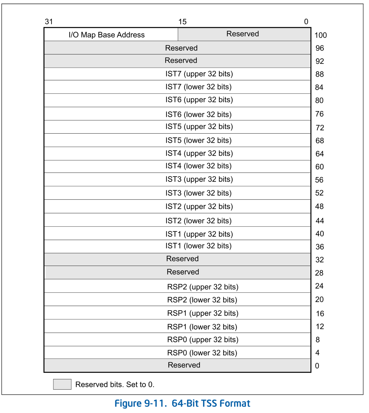 64-Bit TSS Format. SDM Vol.3A Figure 9-11.
The address of the TSS is specified by the TSS Descriptor. The TSS descriptor has the same format as the LDT Descriptor. Note that, unlike other segment descriptors, the size of the TSS descriptor is 16 bytes.
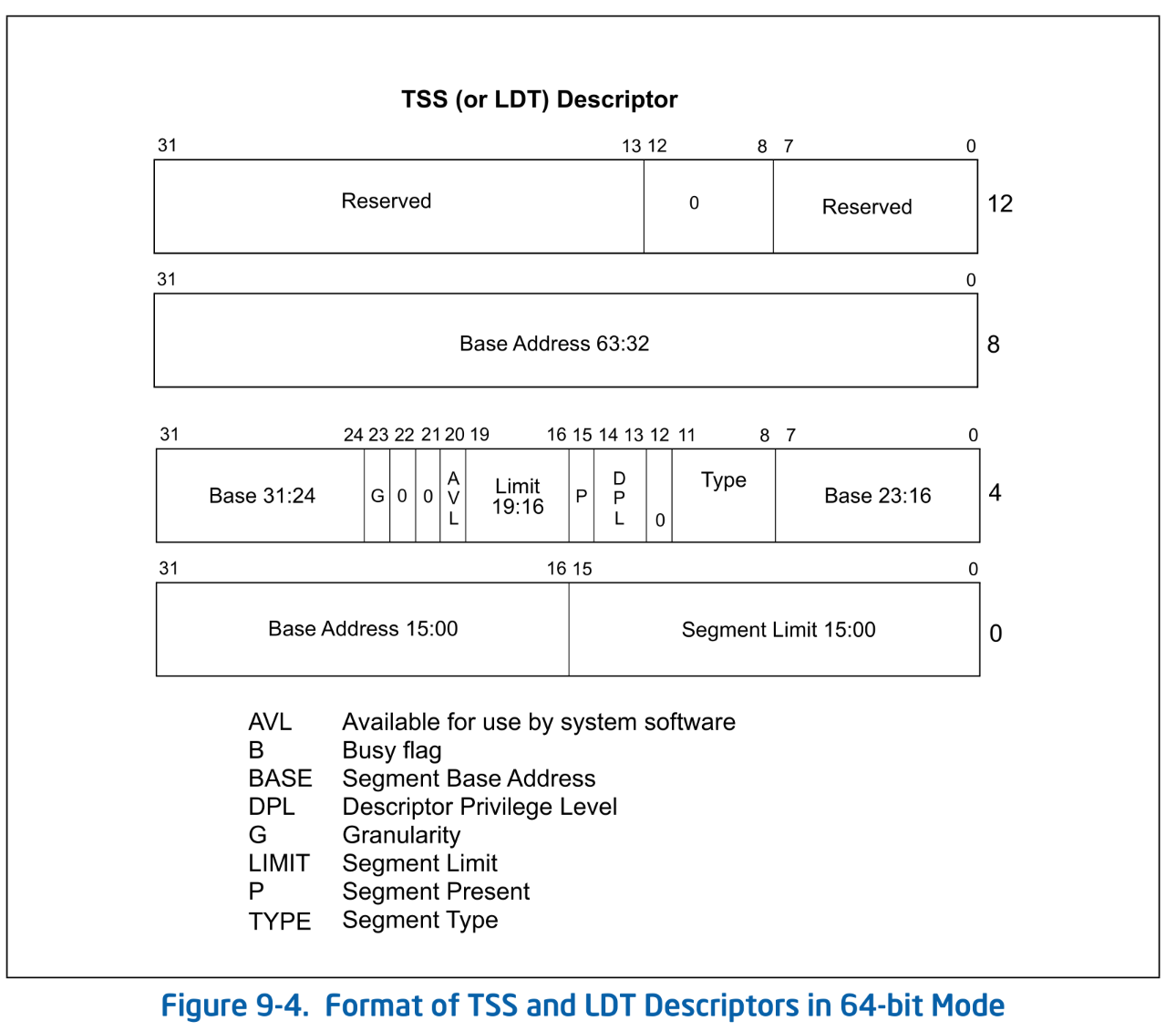 Format of TSS and LDT Descriptors in 64-bit Mode. SDM Vol.3A Figure 9-4.
The index of the TSS descriptor in the GDT is stored in the TR: Task Register. The TSS descriptor occupies two entries in the GDT.
Segmentation in 64-bit Mode
So far, we have explained segmentation, but in x64, most of the segmentation functionality is disabled. More precisely, in Intel 64 architecture's 64-bit mode (IA-32e mode's 64-bit mode), segmentation is almost entirely disabled. The Base is interpreted as 0, and checks based on Limit are not performed. Therefore, logical to linear translation does not actually modify the address, effectively treating the memory as a single, flat, and large segment4.
The exceptions are the FS and GS segments. Segmentation can still be configured for these two, and their usage depends on the software. In glibc, FS is used to represent TLS: Thread Local Storage, while Linux Kernel uses GS to represent per-CPU data5.
Even when using FS/GS segments, only the Base part is actually utilized. The Base part in the hidden part of FS/GS is mapped to model-specific registers (MSRs) called FSBASE and GSBASE. Besides the traditional method of setting the Base by writing to the segment selector (segment register), it is also possible to directly write the Base to FSBASE/GSBASE MSRs. Note that writing to the MSRs using WRMSR is a privileged instruction and comes with a context switch. Therefore, starting with Ivy Bridge, the FSGSBASE extension was introduced, enabling user-land apps to directly access FSBASE / GSBASE via instructions like RDFSBASE / RDGSBASE.
In short, in Ymir, there is almost no need to configure segment settings.
warn
While segmentation is effectively disabled, meaning address translation does not occur, access permission checks for segments are still performed even in 64-bit mode.
Privilege checks are performed based on three values: CPL, DPL, and RPL. This topic can get a bit complex, so if you're interested, please refer to SDM Vol.3A 5.5: PRIVILEGE LEVELS for more details.
Segmentation in Ymir
Ymir only sets up two types of segments: the CS segment and the others. Unlike Linux, we currently don't plan to use GS. Let's configure these two segments in the GDT.
Definition of Basic Structures
Let's define a GDT entry described in Figure 3-8:
pub const SegmentDescriptor = packed struct(u64) {
    /// Lower 16 bits of the segment limit.
    limit_low: u16,
    /// Lower 24 bits of the base address.
    base_low: u24,
    /// Segment is accessed.
    accessed: bool = true,
    /// Readable / Writable.
    rw: bool,
    /// Direction / Conforming.
    dc: bool,
    /// Executable.
    executable: bool,
    /// Descriptor type.
    desc_type: DescriptorType,
    /// Descriptor Privilege Level.
    dpl: u2,
    /// Segment present.
    present: bool = true,
    /// Upper 4 bits of the segment limit.
    limit_high: u4,
    /// Available for use by system software.
    avl: u1 = 0,
    /// 64-bit code segment.
    long: bool,
    /// Size flag.
    db: u1,
    /// Granularity.
    granularity: Granularity,
    /// Upper 8 bits of the base address.
    base_high: u8,
};

pub const DescriptorType = enum(u1) {
    system = 0,
    code_data = 1,
};

pub const Granularity = enum(u1) {
    byte = 0,
    kbyte = 1,
};
Here is a table explaining the fields that haven't been covered so far:
| Field | Description |
|---|---|
accessed, rw, dc, executable | Type field. Access permission and status 6. dc is a type of segment (Code or Data). |
desc_type | Application Descriptor or System Descriptor7. |
present | false if the segment is swapped out. |
avl | Bit that software can use. |
db | The meaning varies depending on the Type field. It determines some kind of default size. |
long | Whether the code segment is 64bit. |
Next, we create an entry for TSS. Unlike other descriptors, a TSS descriptor is 16 bytes long, so we define a new struct for it:
const TssDescriptor = packed struct(u128) {
    /// Lower 16 bits of the segment limit.
    limit_low: u16,
    /// Lower 24 bits of the base address.
    base_low: u24,

    /// Type: TSS.
    type: u4 = 0b1001, // tss-avail
    /// Descriptor type: System.
    desc_type: DescriptorType = .system,
    /// Descriptor Privilege Level.
    dpl: u2 = 0,
    present: bool = true,

    /// Upper 4 bits of the segment limit.
    limit_high: u4,
    /// Available for use by system software.
    avl: u1 = 0,
    /// Reserved.
    long: bool = true,
    /// Size flag.
    db: u1 = 0,
    /// Granularity.
    granularity: Granularity = .kbyte,
    /// Upper 40 bits of the base address.
    base_high: u40,
    /// Reserved.
    _reserved: u32 = 0,

    /// Create a new 64-bit TSS descriptor.
    pub fn new(base: Virt, limit: u20) TssDescriptor {
        return TssDescriptor{
            .limit_low = @truncate(limit),
            .base_low = @truncate(base),
            .limit_high = @truncate(limit >> 16),
            .base_high = @truncate(base >> 24),
        };
    }
};
NULL Descriptor
The 0th entry in a GDT is used as NULL Descriptor. The CPU never actually uses the NULL descriptor. A segment selector that points to the NULL descriptor is called a NULL segment selector. Segment Selectors that are not in use, except for CS/SS, can be set to the NULL segment selector. However, attempting to access memory using a NULL segment selector will cause a #GP: General Protection Fault.
Creating GDT Entry
Now, let's initialize the code segment and data segment:
const max_num_gdt = 0x10;

var gdt: [max_num_gdt]SegmentDescriptor align(16) = [_]SegmentDescriptor{
    SegmentDescriptor.newNull(),
} ** max_num_gdt;
The number of GDT entries is variable and can be chosen freely8, so here we arbitrarily set it to 10. We prepare an array of GDT entries of this size. The function newNull() creates an empty (null) entry:
pub fn newNull() SegmentDescriptor {
    return @bitCast(@as(u64, 0));
}

pub fn new(
    rw: bool,
    dc: bool,
    executable: bool,
    base: u32,
    limit: u20,
    dpl: u2,
    granularity: Granularity,
) SegmentDescriptor {
    return SegmentDescriptor{
        .limit_low = @truncate(limit),
        .base_low = @truncate(base),
        .rw = rw,
        .dc = dc,
        .executable = executable,
        .desc_type = .code_data,
        .dpl = dpl,
        .present = true,
        .limit_high = @truncate(limit >> 16),
        .avl = 0,
        .long = executable,
        .db = @intFromBool(!executable),
        .granularity = granularity,
        .base_high = @truncate(base >> 24),
    };
}
Since segment descriptor entries have many fields and are cumbersome to initialize, we also define a helper function new() for convenience.
Let's initialize the required entries. This time, we'll create two entries for the code and data segments, setting CS to point to the former and DS/ES/FS/GS to point to the latter.
pub const kernel_ds_index: u16 = 0x01;
pub const kernel_cs_index: u16 = 0x02;
pub const kernel_tss_index: u16 = 0x03;

pub fn init() void {
    gdt[kernel_cs_index] = SegmentDescriptor.new(
        true,
        false,
        true,
        0,
        std.math.maxInt(u20),
        0,
        .kbyte,
    );
    gdt[kernel_ds_index] = SegmentDescriptor.new(
        true,
        false,
        false,
        0,
        std.math.maxInt(u20),
        0,
        .kbyte,
    );
    ...
}
The only difference between CS and DS is whether they are executable. The .rw flag means writable for data segments and readable for code segments.
Next, let's set up TSS. Since we won't actually use the TSS segment, we'll simply allocate one page of memory as a placeholder and configure the TSS descriptor to point to that area.
/// Unused TSS segment.
const tssUnused: [4096]u8 align(4096) = [_]u8{0} ** 4096;

pub fn init() void {
    ...
    // TSS is not used by Ymir. But we have to set it for VMX.
    setTss(@intFromPtr(&tssUnused));
    ...
}

fn setTss(tss: Virt) void {
    const desc = TssDescriptor.new(tss, std.math.maxInt(u20));
    @as(*TssDescriptor, @ptrCast(&gdt[kernel_tss_index])).* = desc;

    loadKernelTss();
}

fn loadKernelTss() void {
    asm volatile (
        \\mov %[kernel_tss], %%di
        \\ltr %%di
        :
        : [kernel_tss] "n" (@as(u16, @bitCast(SegmentSelector{
            .rpl = 0,
            .index = kernel_tss_index,
          }))),
        : "di"
    );
}
note
Ymir does not implement userland nor provides a separate interrupt stack, so it does not use TSS. However, when performing VM-Entry later, there is a constraint that "the host's TR must not be zero." That's why we create an empty TSS here.
With the GDT initialization complete, we now set GDT register with the address of GDT.
const GdtRegister = packed struct {
    limit: u16,
    base: *[max_num_gdt]SegmentDescriptor,
};

var gdtr = GdtRegister{
    .limit = @sizeOf(@TypeOf(gdt)) - 1,
    .base = undefined,
};

pub fn init() void {
    ...
    gdtr.base = &gdt;
    am.lgdt(@intFromPtr(&gdtr));
    ...
}
GDTR holds only the address and size of GDT. Ideally, the address should be a physical address, but since Ymir currently uses the straight mapping provided by UEFI, the virtual and physical addresses are identical. Therefore, the virtual address &gdt is used directly as the physical address.
warn
Ideally, I wanted to initialize gdtr with .base = &gdt, but due to a bug in Zig or LLVM9, that causes an error. Therefore, I had no choice but to assign &gdt inside the init() function.
am.lgdt() is an assembly function that simply executes LGDT instruction.
pub inline fn lgdt(gdtr: u64) void {
    asm volatile (
        \\lgdt (%[gdtr])
        :
        : [gdtr] "r" (gdtr),
    );
}
Flushing Segment Register
Although the GDT initialization is complete, the new segment settings are not yet applied. This is because the segment Base is cached in the hidden part of the segment register. By updating the selector part of the segment register with the new GDT index and flushing the hidden part, the new segment settings will finally take effect:
fn loadKernelDs() void {
    asm volatile (
        \\mov %[kernel_ds], %di
        \\mov %%di, %%ds
        \\mov %%di, %%es
        \\mov %%di, %%fs
        \\mov %%di, %%gs
        \\mov %%di, %%ss
        :
        : [kernel_ds] "n" (@as(u16, @bitCast(SegmentSelector{
            .rpl = 0,
            .index = kernel_ds_index,
          }))),
        : "di",
    );
}
You can directly load the segment register using MOV instruction. Since DI register is used for the assignment, it is marked as clobbered to inform the compiler accordingly.
However, you cannot load the CS register directly with a MOV instruction. Instead, you set CS by performing a Long Return.
fn loadKernelCs() void {
    asm volatile (
        \\
        // Push CS
        \\mov %[kernel_cs], %%rax
        \\push %%rax
        // Push RIP
        \\leaq next(%%rip), %%rax
        \\pushq %%rax
        \\lretq
        \\next:
        \\
        :
        : [kernel_cs] "n" (@as(u16, @bitCast(SegmentSelector{
            .rpl = 0,
            .index = kernel_cs_index,
          }))),
    );
}
The lret instruction pops CS and RIP from the stack and loads them into the registers. Since we don't want to change RIP, we push the address immediately following the lret instruction onto the stack, effectively updating only CS register.
With this, new GDT will take effect. Make sure to call this from the init() function.
pub fn init() void {
    ...
    loadKernelDs();
    loadKernelCs();
    loadKernelTss();
}
Summary
Call the implemented GDT initialization function from kernelMain().
arch.gdt.init();
log.info("Initialized GDT.", .{});
When you run it, visually nothing will change, but the execution should reach the HLT loop. At this point, open the QEMU monitor and check the registers.
QEMU 8.2.2 monitor - type 'help' for more information
(qemu) info registers

CPU#0
RAX=deadbeefcafebabe RBX=000000001fe91f78 RCX=00cf93000000ffff RDX=ffffffff801003f8
RSI=0000000000000030 RDI=000000000000000a RBP=000000001fe908a0 RSP=ffffffff80106f10
R8 =000000001fe8ff8c R9 =000000001f9ec018 R10=000000001fae6880 R11=0000000089f90beb
R12=000000001feaff40 R13=000000001fe93720 R14=ffffffff801003c0 R15=00000000ff000000
RIP=ffffffff80100331 RFL=00000046 [---Z-P-] CPL=0 II=0 A20=1 SMM=0 HLT=1
ES =0008 0000000000000000 ffffffff 00c09300 DPL=0 DS   [-WA]
CS =0010 0000000000000000 ffffffff 00a09b00 DPL=0 CS64 [-RA]
SS =0008 0000000000000000 ffffffff 00c09300 DPL=0 DS   [-WA]
DS =0008 0000000000000000 ffffffff 00c09300 DPL=0 DS   [-WA]
FS =0008 0000000000000000 ffffffff 00c09300 DPL=0 DS   [-WA]
GS =0008 0000000000000000 ffffffff 00c09300 DPL=0 DS   [-WA]
LDT=0000 0000000000000000 0000ffff 00008200 DPL=0 LDT
TR =0000 0000000000000000 0000ffff 00008b00 DPL=0 TSS64-busy
GDT=     ffffffff80108010 0000007f
IDT=     000000001f537018 00000fff
CR0=80010033 CR2=0000000000000000 CR3=000000001e4d6000 CR4=00000668
The leftmost 4 nibbles of the segment register value represent the segment selector. Within the selector, the lower 3 bits are RPL/TI, and the remaining bits represent the GDT index. For CS, the selector is 0x10, meaning the index is 0x02. For DS/ES/FS/GS, the selector is 0x08, meaning the index is 0x01. These correspond to the values set in kernel_ds_index and kernel_cs_index respectively. This confirms that the prepared GDT has been correctly applied.
In this chapter, we performed the initialization of GDT. Since segmentation is mostly unused in x64 64-bit mode, we only set up two segments. TGDT provided by UEFI is no longer used, so its memory region is now freely available for Ymir. In the next chapter, we will replace the IDT, another structure provided by UEFI, with Ymir's own implementation.
Similarly, there is a structure called LDT: Local Descriptor Table used for setting up segments, but Ymir only uses GDT.
The size of the physical address space in x64 (Intel64) is implementation-dependent. You can obtain the actual size using CPUID 0x80000008. On recent CPUs, it is often 46 bits.
Since logical to linear translation is not performed, in this series, both logical and linear addresses are collectively referred to as virtual addresses.
This 4-bit field varies depending on whether the Descriptor Type is application (code/data) or system. Since this series does not cover system segments, only the fields for application segments are defined.
System descriptors include LDT, TSS, call-gate, interrupt-gate, trap-gate, and task-gate descriptors.
However, the maximum limit in IA-32e mode is \(2^{13} = 8192\) entries.