PIC
In the Interrupt and Exception chapter, we prepared to receive interrupts by setting up the IDT. However, since the external interrupt configuration has not been done yet, interrupts do not occur in the first place. In this chapter, we will initialize and configure PIC: Programmable Interrupt Controller. This enables receiving interrupts from external devices such as timers and keyboards.
important
The source code for this chapter is in whiz-ymir-pic branch.
Table of Contents
- Intel 8259 PIC
- Command Words
- Initialization of PIC
- Helper Functions
- Unmask Interrupts
- Summary
- References
Intel 8259 PIC
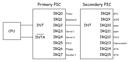
The PIC we deal with in this series is Intel 8259A. Modern Intel CPUs reportedly include two 8259A-equivalent controllers, referred to as the Master PIC and Slave PIC. In this series, we call them the Primary PIC and Secondary PIC. Each has eight input lines called Interrupt Requested Lines (IRQs), and the secondary is cascaded to the primary. Nowadays, the APIC: Advanced Programmable Interrupt Controller is widely used instead of 8259 PIC. Although the PIC chip itself is rarely integrated nowadays, the southbridge still provides 8259A-equivalent functionality.
 Functional Overview of 8259A PIC
The internal structure of each PIC is illustrated in the following conceptual diagram:
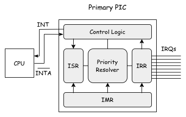 Functional Overview of the Internal Structure of 8259A PIC
IRR
IRR: Interrupt Request Register is a register that holds interrupt requests received by the PIC. When the IRR contains any interrupt requests, the PIC sends an INT signal to the CPU to request an interrupt. The IRR can always be read by a CPU.
ISR
ISR: In-Service Register holds the interrupt requests that the CPU has accepted for processing. When the CPU acknowledges an interrupt request, it sends the \(\overline{INTA}\) signal to the PIC1. Upon receiving this signal, the Priority Resolver selects the highest-priority interrupt request from the IRR. The corresponding bit for the selected IRQ is set in the ISR, and the same bit is cleared from the IRR. By default, IRQ0 has the highest priority, and IRQ7 the lowest. When a bit is set in the ISR, all IRQs with lower priority are automatically masked out. The ISR can always be read by a CPU.
IMR
IMR: Interrupt Mask Register is used to mask interrupt requests received by the PIC. Any bit set in the IMR causes the corresponding bit in the IRR to be ignored.
Command Words
8259A PIC accepts commands from a CPU known as CW: Command Words2. There are two types of CWs: ICW: Initialization Command Words, which are used to initialize the PIC, and OCW: Operation Command Words, which are used to control the PIC after initialization. Both are executed by sending a 1-byte value to the PIC. In the following sections, we denote the N-th bit of this byte as D[N].
ICW
ICWs are commands used to initialize the PIC. Once the initialization sequence begins, the following command words are interpreted as ICWs. The sequence consists of four command words, each configuring specific settings. While (almost) all configuration options are described below for completeness, Ymir only uses a small subset of them.
ICW1
Enter PIC initialization mode. When D[4] is set to 1, the command is interpreted as ICW1. The following configurations are made:
- Whether ICW4 is required
- Single mode or cascade mode (whether there's one PIC or a primary-secondary pair)
- Level-triggered or edge-triggered
ICW2
The command following ICW1 is interpreted as ICW2. It sets the interrupt vector offset, determining how IRQs are mapped to interrupt vectors on the CPU. For example, if 0x20 is specified, IRQ1 will correspond to interrupt vector 0x21, IRQ2 to 0x22, and so on.
ICW3
The command following ICW2 is interpreted as ICW3. When sent to the primary PIC, it specifies which IRQ lines are connected to the secondary PIC. When sent to a secondary PIC, it specifies the Cascade ID, indicating which IRQ line on the primary it is connected to.
ICW4
The command following ICW3 is interpreted as ICW4. It configures the following settings:
- Mode: 8086/8088 mode or MCS-80/85 mode
- EOI: Auto-EOI or normal EOI (we'll cover later)
- Buffering mode
- Nest mode
OCW
After initializing the PIC, commands can be issued to configure or modify its operational state.
OCW1
Set the IMR (Interrupt Mask Register). Each bit in the IMR masks the corresponding IRQ.
OCW2
Run the below:
- EOI: Covered later.
- Rotate: Enables priority rotation, so that lower-priority IRQs are processed first.
- Set: Set the priority.
OCW3
Primarily used to read the values of IRR and ISR.
Initialization of PIC
With the above knowledge in mind, let's proceed to initialize the PIC. In x64, both the primary and secondary PICs have their own command ports and data ports3. The I/O ports are as follows:
const primary_command_port: u16 = 0x20;
const primary_data_port: u16 = primary_command_port + 1;
const secondary_command_port: u16 = 0xA0;
const secondary_data_port: u16 = secondary_command_port + 1;
First, let's define ICW:
const icw = enum { icw1, icw2, icw3, icw4 };
const Icw = union(icw) {
    icw1: Icw1,
    icw2: Icw2,
    icw3: Icw3,
    icw4: Icw4,

    const Icw1 = packed struct(u8) {
        /// ICW4 is needed.
        icw4: bool = true,
        /// Sigle or cascade mode.
        single: bool = false,
        /// CALL address interval 4 or 8.
        interval4: bool = false,
        /// Level triggered or edge triggered.
        level: bool = false,
        /// Initialization command.
        _icw1: u1 = 1,
        /// Unused in 8085 mode.
        _unused: u3 = 0,
    };
    const Icw2 = packed struct(u8) {
        /// Vector offset.
        offset: u8,
    };
    const Icw3 = packed struct(u8) {
        /// For primary PIC, IRQ that is cascaded.
        /// For secondary PIC, cascade identity.
        cascade_id: u8,
    };
    const Icw4 = packed struct(u8) {
        /// 8086/8088 mode or MCS-80/85 mode.
        mode_8086: bool = true,
        /// Auto EOI or normal EOI.
        auto_eoi: bool = false,
        /// Buffered mode.
        buf: u2 = 0,
        /// Special fully nested mode.
        full_nested: bool = false,
        /// ReservedZ.
        _reserved: u3 = 0,
    };
};
Icw is a tagged union. Similar to a C union, a union always has exactly one active field. Accessing a field that is not active will result in a runtime error in Debug builds, and undefined behavior in other builds.
Similarly, OCW is also defined as follows:
const ocw = enum { ocw1, ocw2, ocw3 };
const Ocw = union(ocw) {
    ocw1: Ocw1,
    ocw2: Ocw2,
    ocw3: Ocw3,

    const Ocw1 = packed struct(u8) {
        /// Interrupt mask.
        imr: u8,
    };
    const Ocw2 = packed struct(u8) {
        /// Target IRQ.
        level: u3 = 0,
        /// ReservedZ.
        _reserved: u2 = 0,
        /// EOI
        eoi: bool,
        /// If set, specific EOI.
        sl: bool,
        /// Rotate priority.
        rotate: bool = false,
    };
    const Ocw3 = packed struct(u8) {
        /// Target register to read.
        ris: Reg,
        /// Read register command.
        read: bool,
        /// Unused in Ymir.
        _unused1: u1 = 0,
        /// Reserved 01.
        _reserved1: u2 = 0b01,
        /// Unused in Ymir.
        _unused2: u2 = 0,
        /// ReservedZ.
        _reserved2: u1 = 0,

        const Reg = enum(u1) { irr = 0, isr = 1 };
    };
};
Note that for both ICW and OCW, fields that are fixed by hardware or not used in Ymir are set to default values.
Next, we define helper functions to send these CWs to the PIC:
const am = @import("asm.zig");

fn issue(cw: anytype, port: u16) void {
    const T = @TypeOf(cw);
    if (T != Icw and T != Ocw) {
        @compileError("Unsupported type for pic.issue()");
    }
    switch (cw) {
        inline else => |s| am.outb(@bitCast(s), port),
    }
    am.relax();
}
issue() guarantees that it only accepts Icw or Ocw. A switch on a union can change behavior based on the active field. In this case, we want to apply @bitCast() to whichever field is active and execute OUTB the same way. Therefore, we use inline else to unconditionally extract the field inside the union.
Using this function, the PIC initialization function can be written easily:
pub const primary_vector_offset: usize = 32;
pub const secondary_vector_offset: usize = primary_vector_offset + 8;

pub fn init() void {
    am.cli();
    defer am.sti();

    // Start initialization sequence.
    issue(Icw{ .icw1 = .{} }, primary_command_port);
    issue(Icw{ .icw1 = .{} }, secondary_command_port);

    // Set the vector offsets.
    issue(Icw{ .icw2 = .{ .offset = primary_vector_offset } }, primary_data_port);
    issue(Icw{ .icw2 = .{ .offset = secondary_vector_offset } }, secondary_data_port);

    // Tell primary PIC that there is a slave PIC at IRQ2.
    issue(Icw{ .icw3 = .{ .cascade_id = 0b100 } }, primary_data_port);
    // Tell secondary PIC its cascade identity.
    issue(Icw{ .icw3 = .{ .cascade_id = 2 } }, secondary_data_port);

    // Set the mode.
    issue(Icw{ .icw4 = .{} }, primary_data_port);
    issue(Icw{ .icw4 = .{} }, secondary_data_port);

    // Mask all IRQ lines.
    setImr(0xFF, primary_data_port);
    setImr(0xFF, secondary_data_port);
}

fn setImr(imr: u8, port: u16) void {
    issue(Ocw{ .ocw1 = .{ .imr = imr } }, port);
}
Since there is currently no interrupt handler prepared, when an interrupt occurs from IRQ, unhandledHandler() is called as the interrupt handler. To avoid this, interrupts are disabled at the very beginning. The disabled interrupts should be re-enabled when returning from init(). This kind of RAII pattern can be implemented in Zig using defer.
The commands are used while setting only those Icw fields that don't have default values. ICW1 indicates that ICW4 is required. ICW2 sets the IRQ and interrupt vector offset, which will be explained later. ICW3 configures the connection between the primary and secondary PICs. Since the 8259A connects the secondary PIC to IRQ2, the primary PIC is set with 0b100 == 4. ICW4 specifies normal EOI, which will also be discussed later.
Vector Offset
By default, IRQ-N triggers the Nth interrupt vector. This is fine in real mode, but in protected mode, vectors 0 through 31 are reserved by Intel. This causes a direct conflict. Looks like IBM really messed up here.
Since there's no choice, most OSes including Linux remap IRQ interrupt vectors to different vectors. In Ymir, the offsets 32 and 40 are set for the primary and secondary PICs respectively. This makes IRQ-N trigger interrupt vector 32 + N. This offset is specified using ICW2.
EOI
EOI: End of Interrupt is a notification to the PIC allowing it to send further interrupts. There are two EOI modes, which can be configured via ICW4:
- Automatic EOI: When the PIC notifies the CPU of an interrupt and receives the final \( \overline{INTA} \) signal from the CPU, EOI is automatically and implicitly sent to the PIC .
- Normal EOI: CPU explicitly sends a EOI command.
Ymir adopts a normal EOI. It has two types of notification:
- Specific EOI: Send an EOI for the specific IRQ.
- Non-Specific EOI: CPU does not specify IRQ number. IRQ with the highest priority is automatically selected.
Ymir uses a specific EOI, which is sent via OCW2. At this time, the 3-bit level field specifies the IRQ number. The specified IRQ is then cleared from the ISR.
When the interrupt being handled belongs to the secondary PIC's IRQ8–IRQ15 range, the EOI must be sent to both the primary and secondary PICs. For the primary PIC, the EOI is sent to the cascaded IRQ2 where the secondary PIC is connected.
Helper Functions
The PIC initialization is complete. Next, we'll implement helper functions to operate the PIC from other files.
First, define the enum for IRQ:
pub const IrqLine = enum(u8) {
    timer = 0,
    keyboard = 1,
    secondary = 2,
    serial2 = 3,
    serial1 = 4,
    parallel23 = 5,
    floppy = 6,
    parallel1 = 7,
    rtc = 8,
    acpi = 9,
    open1 = 10,
    open2 = 11,
    mouse = 12,
    cop = 13,
    primary_ata = 14,
    secondary_ata = 15,

    /// Return true if the IRQ belongs to the primary PIC.
    pub fn isPrimary(self: IrqLine) bool {
        return @intFromEnum(self) < 8;
    }

    /// Get the command port for this IRQ.
    pub inline fn commandPort(self: IrqLine) u16 {
        return if (self.isPrimary()) primary_command_port else secondary_command_port;
    }

    /// Get the data port for this IRQ.
    pub inline fn dataPort(self: IrqLine) u16 {
        return if (self.isPrimary()) primary_data_port else secondary_data_port;
    }

    /// Get the offset of the IRQ within the PIC.
    pub fn delta(self: IrqLine) u3 {
        return @intCast(if (self.isPrimary()) @intFromEnum(self) else (@intFromEnum(self) - 8));
    }
};
When handling IRQ numbers, it is often preferable to treat them as separate sequences (0–7) for each PIC rather than a continuous sequence (0–15) combining primary and secondary. The delta() function returns the value as-is for the primary PIC, and subtracts 8 for the secondary.
Define a function that sets the corresponding IMR (mask) for a given IrqLine:
pub fn setMask(irq: IrqLine) void {
    const port = irq.dataPort();
    setImr(am.inb(port) | bits.tobit(u8, irq.delta()), port);
}

pub fn unsetMask(irq: IrqLine) void {
    const port = irq.dataPort();
    setImr(am.inb(port) & ~bits.tobit(u8, irq.delta()), port);
}
Each PIC has its own IMR, so IRQs 0-7 and 8-15 need to be configured separately. By using the helper functions prepared earlier, specifying ports for the primary and secondary PICs becomes straightforward.
Finally, define a function that sends an EOI notification for the specified IrqLine:
pub fn notifyEoi(irq: IrqLine) void {
    issue(
        Ocw{ .ocw2 = .{ .eoi = true, .sl = true, .level = irq.delta() } },
        irq.commandPort(),
    );
    if (!irq.isPrimary()) {
        issue(
            Ocw{ .ocw2 = .{ .eoi = true, .sl = true, .level = 2 } },
            primary_command_port,
        );
    }
}
As mentioned earlier, EOIs for the secondary must be sent to both the primary and secondary PICs.
Unmask Interrupts
Let's do the PIC initialization in kernelMain() (don't forget to export pic.zig in arch.zig):
arch.pic.init();
log.info("Initialized PIC.", .{});
With this, the PIC initialization is complete. However, running it won't change anything compared to before. That's because all IRQs are still masked by the IMR, so no IRQ will trigger interrupts. To conclude this chapter, let's try enabling serial interrupts.
First, define an interrupt handler for the serial port. Ymir itself doesn't implement any functionality to process serial input. So, for now, we prepare an interrupt handler that simply logs the event and then sends an EOI:
fn blobIrqHandler(ctx: *arch.intr.Context) void {
    const vector: u16 = @intCast(ctx.vector - 0x20);
    log.debug("IRQ: {d}", .{vector});
    arch.pic.notifyEoi(@enumFromInt(vector));
}
As implemented in Interrupt and Exception chapter, interrupt handlers receive context information called Context. This includes the interrupt vector. To get the IRQ number, simply subtract the offset set by ICW2 from the interrupt vector. After outputting the calculated IRQ number, send the EOI using notifyEoi().
Next, register this interrupt handler. Since we haven't implemented a function to register interrupt handlers yet, let's implement it here:
pub fn registerHandler(comptime vector: u8, handler: Handler) void {
    handlers[vector] = handler;
    idt.setGate(
        vector,
        .Interrupt64,
        isr.generateIsr(vector),
    );
}
In kernelMain(), register the interrupt handler and instruct the PIC to unmask the serial interrupt:
arch.intr.registerHandler(idefs.pic_serial1, blobIrqHandler);
arch.pic.unsetMask(.serial1);
Just when you think everything is ready, interrupts still won't occur. You need to configure the serial device itself to generate interrupts. Writing the value 0b01 to the serial's IER: Interrupt Enable Register enables interrupts when the device is in an RX-available or TX-available state. TX-available triggers when the serial output completes and the output buffer is ready for new data. RX-available triggers when serial input becomes readable from the buffer:
pub fn enableInterrupt(port: Ports) void {
    var ie = am.inb(@intFromEnum(port) + offsets.ier);
    ie |= @as(u8, 0b0000_0001); // Rx-available
    ie &= ~@as(u8, 0b0000_0010); // ~Tx-available
    am.outb(ie, @intFromEnum(port) + offsets.ier);
}
idefs is an alias of import of interrupts.zig:
const arch = @import("ymir").arch;

pub const user_intr_base = arch.intr.num_system_exceptions;

pub const pic_timer = 0 + user_intr_base;
...
pub const pic_serial1 = 4 + user_intr_base;
Clearing the 1st bit of the IER prevents infinite interrupts. TX-empty occurs when the data for serial output is actually transmitted, and the output buffer is ready for new data. However, since the interrupt handler also outputs serial logs, this triggers TX-empty again. This causes an endless loop of TX-empty → serial log output → TX-empty → ... To avoid this, this interrupt is disabled.
With this, serial interrupts are enabled. Let's actually run it:
[INFO ] main    | Booting Ymir...
[INFO ] main    | Initialized GDT.
[INFO ] main    | Initialized IDT.
[INFO ] main    | Initialized page allocator.
[INFO ] main    | Reconstructing memory mapping...
[INFO ] main    | Initialized general allocator.
[INFO ] main    | Initialized PIC.
[DEBUG] main    | IRQ: 4
After seeing the message Initialized PIC, pressing any key outputs IRQ: 4. This confirms that the serial interrupt is properly occurring, proving that the PIC configuration is working correctly.
Regarding the IER set in enableInterrupt(), please remove the code that disables TX-empty and instead enable it. In this series, when Ymir virtualizes CPUs, all serial operations are virtualized. During this process, the IER is fixed to enable only TX-empty and RX-available, preventing the guest from modifying it. Therefore, Ymir as the host needs to set the IER in advance:
ie |= @as(u8, 0b0000_0011); // Tx-empty, Rx-available
Also, while we're at it, let's unmask PIT interrupt as well:
arch.intr.registerHandler(idefs.pic_timer, blobIrqHandler);
arch.pic.unsetMask(.timer);
log.info("Enabled PIT.", .{});
Although the PIT is not explicitly configured, it appears to be running by default (or thanks to UEFI settings). Running as-is should continuously output IRQ: 0 at regular intervals.
Finally, since logging from both the timer and serial interrupt handlers can be very noisy, please remove the log.debug() calls.
Summary
In this chapter, we initialized the Intel 8259A PIC and enabled interrupts. We unmasked the timer and serial interrupts and confirmed that the interrupt handlers are actually called. While Ymir does not directly handle IRQs, configuring the PIC on the host side is necessary for virtualizing part of the PIC for the guest.
And with this, the implementation of the Ymir Kernel part is complete! Despite the title "Writing Hypervisor," these chapters covered many aspects not directly related to hypervisor. However, writing a bare-metal hypervisor starts with writing a bare-metal OS. Now that we've laid the OS foundation up to this point, the next chapters will finally dive into hypervisor itself. For today, make sure to stay warm and get some rest early.
References
- 8259A PROGRAMMABLE INTERRUPT CONTROLLER (8259A/8259A-2) - Intel
- 8259 PIC - OSDev Wiki
- パソコンのレガシィI/O活用大全 - 桑野 雅彦
In reality, after the CPU accepts an interrupt and sends the \( \overline{INTA} \) signal to set the ISR, it sends an additional \( \overline{INTA} \) signal. This causes the PIC to place the vector number of the processed interrupt into a buffer called the Data Bus Buffer. When Auto-EOI is enabled, the ISR is cleared at this point.
Command Words can be interpreted more like registers than instructions. However, unlike typical I/O mapped registers, note that writing to the same I/O port may target different command words depending on the context.
When sending through the command port, \( A_0 \) is 0, and when sending through the data port, it becomes 1.